Centrifugal Compressor Aerodynamic Testing
Centrifugal Compressor Aerodynamic Testing article provides information about ASME PTC 10 and as per API Std. 617 requirements.
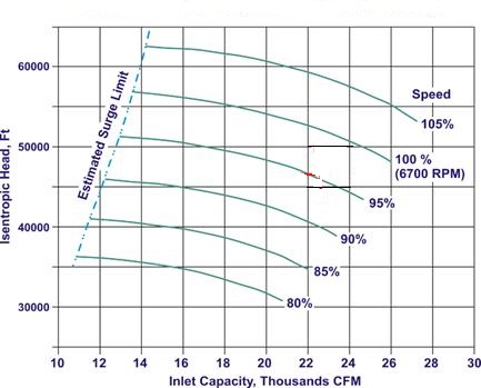
The standard requires minimum 5 datapoints shall be taken for each shaft speed including of surge point and overload point and the performance curve shall be provided by Isentropic head vs. volumetric flowrate. The isentropic head will be on the verticle axis and volumetric flow in the horizontal axis.

What is the surge point on centrifugal compressor aerodynamic testing? The volumetric flow rate is too much low that causes instability in the compressor. This situation happens by reducing flowrate through turning discharge valve "near to close." You experience high noise and vibration at this flowrate in the compressor.
What is the overload point on centrifugal compressor aerodynamic testing? The highest amount of volumetric flowrate that compressor performance curve ends (from right side of the curve). This point also is named choke point. The performance curve shall provide information such as isotropic head, efficiency, power consumption, etc. from the surge point to the overload (choke) point.
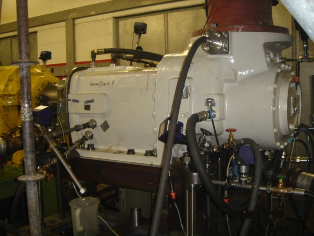
Centrifugal Compressor Aerodynamic Testing by Air
The compressor is subjected to the aerodynamic testing at the open air condition. It meanes the suction and discharge of the compressor are open to the atmosphere.
The compressor runs at the design speed, and the test is started with maximum flow rate (this is the overload (choke) point with the maximum opening of discharge valve). Then the isentropic head is measured at the overload point. (please note the isentropic head represents the discharge pressure)
In next step, the volumetric flowrate is reduced a little bit (by the adjusting of discharge valve), and another point is taken, and the isentropic head is recorded at this point as well.
The process is continued until 5 data points are taken. It means you have 5 known flowrates and 5 known isentropic heads and you can draw the head-flowrate curve. The test engineer runs the compressor at each datapoint for 30 minutes to get everything stabilized and then gets the readings.
The process is continued to identify surge point. The volumetric head is reduced until a high noise and spike in the vibration observed. This point is the surge point, and the head is measured at this point. This point is the lowest flowrate and highest isentropic head, and as mention in above, the compressor is unstable at this flowrate value.
The above-mentioned process gives you one curve, but this is not enough, the test shall be repeated in different shaft speeds and datapoints shall be taken for each shaft speed in a similar way. The test is conducted in several shaft speed, and you can draw the surge like the following figure.

Now, you need to verify the test result. You will not be able to use of datasheet information since the datasheet information provided for natural gas with field operating condition, but you tested with air. Besides your compressor suction pipe and discharge pipe was open to the atmosphere. So the condition between the test and field was completely different, and datasheet can not be used for test result verification.
The manufacturer design engineer provides an estimated air performance test curve (obtained from engineering calculation) that you can use for verification. The curve shall be verified aginst approved procedure and indicated acceptance range. The isentropic head can have plus/minus 2% variation normally.
So you need to put "estimated curve" and "tested curve" side by side and match them and see how much isentropic head is different in individual flowrates values.
In this verification; 1) "rated flowrate" and its isentropic head at the rated shaft speed 2) surge points "flowrates" and "isentropic heads" shall be verified.
This is the way we check the test report. However, the testing software indicates the variation between the estimated curve and tested curve by values and numbers in tabulated format.
The equivalent values obtained from the test can be converted to the field values by engineering calculation that normally is done by engineering software.
The power consumption and vibration values also are provided and shall be checked with estimated values. The vibration FFT plots can be verified through API 617 values.
The compressor efficiency cannot be measured by centrifugal compressor aerodynamic test by air medium and with the open air system.
Closed Loop Test in the Centrifugal Compressor Aerodynamic Testing
Based on customer requirements, the closed loop test might be done in addition to the air test. The compressor efficiency can be measured by closed loop test, and testing condition and variables are much closer to the actual parameters in the field.
The difference between the centrifugal compressor aerodynamic testing by air and closed loop system is on the suction and discharge pipes. In closed loop system, the compressor suction connected to the gas source by the inlet pipe and compressor discharge connected to the closed loop system that simulates actual condition.
The test gas can not be real field gas because we can not have that gas at the manufacturing facility. Typically nitrogen, propane or carbon dioxide are used as the test gas. Again since the gas is different, the simulation is performed to identify equivalent field values.
The performance curve shall be verified aginst of the estimated closed loop performance test curve. The efficiency can be measured and is converted to the equivalent field value.
The closed loop test gives you this opportunity to verify the test results with approved datasheet values. By checking test report with the datasheet, you make sure the compressor have the same specification as indicated in the datasheet and other purchase documents.
Free newsletter!
Sign up to receive my monthly newsletter covering all the latest courses and updates.


New! Comments
Have your say about what you just read! Leave me a comment in the box below.