Third Party Inspection for Power Transformer - Procedure
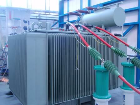
The Third Party Inspection for power transformer is a sample procedure for power transformer inspection and power transformer testing in the manufacturing shop. This article should be reviewed with power transformer inspection and test plan.
This content guides you through all the necessary stages in the production of the power transformers, including the raw material, final inspection, preservation and packing, and dispatch to site. You need to take this point into account: this article is written for a typical power transformers and might not be detailed for special cases.
All power transformers inspection and testing is done against the approved drawings, purchase order specifications, purchasers or company standards, and within the practices and rules of the country, state or province and any government decrees, laws, ordinance or regulation as may apply.
The applicable codes and specifications for a power transformers that is under the construction process is:

- Design code
- Purchase order specification
- Purchaser's standards
- Approved drawings
The applicable codes and standards may be based on any international standards. This content is general and can be useful for all recognized standards.
Required Documents for Third Party Inspector Review:
The list of documents normally is agreed upon in the Pre-Inspection meeting, which is held several weeks before the actual commencement of the inspection work. The parties that participate in this meeting are the manufacturer, purchaser and third party inspection agency representatives.
These are the list of documents that are normally agreed upon to be presented to the inspector:
- Power Transformer Purchase Order or Contract
- Power Transformer Manufacture Quality Control Plan
- Power Transformer Inspection and Test Plan
- Power Transformer Data Sheet
- Power Transformer Approved Drawings, (arrangements, schematics, wiring, single line)
- Power Transformer Weld Procedures and Procedure Qualification Records (if applicable)
- Power Transformer Material Test Reports
- Power Transformer Calibration Certificates for Test Equipment
- Power Transformer Special Procedures
- Power Transformer Special Qualifications
- Power Transformer Preparation and Painting/finishing Procedure
- Power Transformer Packing List
Third Party Inspection for Power Transformer - Material Inspection
The first actual inspection work in the power transformers is the materials inspection. The original or authenticated copies of mill certificates of material normally are available at the manufacturer's premises. The third party inspector examines these certificates for compliance with specifications, and where appropriate, drawings.
The review includes checks on:
- Maker’s name and location
- Certificate number, grade
- Batch number
- Chemical composition
- Mechanical Properties
- Cast number (for metal parts)
- Heat treatment condition
- Surface finish (if required)
- Structural observations, notable defects
Ancillary items may be supported by test certification, or by certificates of conformity. It is necessary the content of certification to be appropriate to the required scope of the items. Instruments normally are supported by instrument calibration records.
Then the inspector witnesses the materials identification on the certificates against the materials marking. It is also necessary to check these with the power transformers drawing datasheet, material list and other specifications as appropriate.
Visual inspection for surface finish and probable defects is done and dimensional compliance with specification need to be controlled, as well.
When the third party inspector carries out the material inspection, then provides the inspection visit report (IVR), the report contains the following items:
- Confirmation of satisfactory document review
- Record of the endorsement of certification reviewed/witnessed
- Record of all non-conformities
- Record of any tests witnessed and the result
Third Party Inspection for Power Transformer – Fabrication
When the power transformers material inspection being carried out, and the results were satisfactory or non-conformities were closed by remedial action, then the power transformers manufacturer will start fabrication/ welding.
The third party inspector checks the following points on the power transformers, based on the inspection and test plan (ITP), which has already been agreed upon between the purchaser and the power transformers manufacturer.
The inspection scope is determined in the ITP. Some purchasers prefer to have stringent controls and assign the TPI for more “hold or witness points” for inspection and test activities, and some others prefer less “hold or witness points” and assign the TPI much more work in the “review document.”
This depends in the inspection budget, which purchasers assign for inspection. Much more inspection will have a much larger cost and less risk, and conversely, less inspection will have less cost but more risks.

The third party inspector checks following in accordance of approved drawings and applicable standards:
- Fabrication, protective finishes and cleanliness of all tank areas and of formers and frames
- Correctness of windings, terminations, insulation, spacing and general construction
- Freedom from damage (with particular attention to insulation), contamination and foreign objects
- Manually check security of wedges
Construction Check
The third party inspector checks following in accordance of approved drawings and applicable standards:
- Paint using specified colour swatch, measure thickness, if specified
- Name plate
- Outline dimensions, interface dimensions and clearances and other specified dimensions
General Arrangement Check
The third party inspector checks that all instruments, terminal boxes, compartments, control switches etc. are correctly rated and are correctly located, with specified labelling
The inspection is done based of approved drawings.
Third Party Inspection for Power Transformer Winding Resistance Test
Resistance of all windings are measured, with winding temperature at recorded ambient, using a milliohmeter and acceptance criteria is power transformer datasheet.
Winding Ratios Test
Primary to secondary winding ratios, for each phase, for all tappings are measured using a ratiometer and acceptance criteria is power transformer datasheet.
Third Party Inspection for Power Transformer - Temperature Rise Test -Type Test
The transformer is subjected to full load current at rated voltage (various loading methods may apply), with “normal” tap selected, with monitoring of oil temperature (lower and upper); cooling air temperature measured by at least 3 thermometers in liquid providing a time constant of 2H, placed at 1 to 2 metres from the cooling surface for “Air Natural” cooling (for “Air Forced” cooling, the thermometers should be within the air input flow, at 1 to 2 metres).
Conditions are maintained until oil temperature stabilises (generally specified as less than 3°C rise in 1 hour).
Winding temperatures are then ascertained using the resistance method:
T2= R2/R1(235+T1)-235 for copper
Where R1 is the cold resistance and R2 is the resistance, with cooling curve corrections applied, after switching off.
Acceptance criterion is in according of applicable specification and datasheet.
Third Party Inspection for Power Transformer - Load Loss Test (Copper Loss)-Type Test
Shorting links are applied (either to the primaries or to the secondaries, dependant on test supply voltages). Voltage supply is applied to the opposing windings and increased until rated current is achieved. Input and output powers are measured and loss calculated.
Acceptance criterion is in according of applicable specification and datasheet.
No Load Loss Test (Iron Loss)-Type Test
Rated voltage is applied to primaries or secondaries, with the opposing windings open circuit. Input and output powers are monitored and loss calculated.
Acceptance criterion is in according of applicable specification and datasheet.
Third Party Inspection for Power Transformer Efficiency –Type Test
Efficiency is calculated from the losses.
Third party inspector reviews the calculation in manufacture quality control records.
Power Transformer - Induced Overvoltage Withstand Test (Overpotential Test)
There are three methods; dependent on winding category, the test would be acceptable if no collapse occurs in test voltage.
Third Party Inspection for Power Transformer - Dielectric Test
Test requirements vary with winding category and acceptable level is in according to applicable standard.
Power Transformer Separate Source Voltage Withstand Test
A single phase AC voltage of power frequency (not less than 80% of the rated frequency) is applied. Peak value is measured. The peak value x sq. rt.2 = test value. The voltage is gradually increased from 1/3 vale and sustained for 60 seconds.
The test is applied between each winding and the terminals of all other windings, core, frame and tank, all connected together to earth.
The test would be acceptable if no collapse occurs in the test voltage.
Third Party Inspection for Power Transformer - Ancillaries Test
Ancillaries normally include “Buchholz” oil pressure protection, temperature monitoring devises and ancillary wiring. These are checked as conforming to drawings. Wiring is subjected to insulation test, where appropriate and withstand test, where appropriate.
Third Party Inspection for Power Transformer - Reporting
The third party inspector provides an Inspection Visit Report (IVR) after each visit, as well as a final report summarizing the activities carried out during the power transformer production in accordance with the contract requirements and circulated within the time limits specified in the contract.
The report is in the format required by the client and clearly indicates final acceptance or rejection of the power transformer.
Third Party Inspection for Power Transformer - Release Note
When required by the contract or purchase order, a release note is issued by the third party inspection agency and given to the manufacturer when the power transformers have been accepted.
Third Party Inspection for Power Transformer - Packing, Marking and Shipping
The following points are checked by the third party inspector for packing and shipment inspection:
- Verify that the packing materials conform to specifications and accepted practice for the mode of transport.
- Verify protection against humidity, abrasion, distortion and other damage
- Verify shipping marks to marking instructions and record.
- Verify handling marks.
Free newsletter!
Sign up to receive my monthly newsletter covering all the latest courses and updates.


New! Comments
Have your say about what you just read! Leave me a comment in the box below.