Piping Hanging and Support Engineering Specification
This article provides you with example piping hanging and support engineering specification that is used in construction of industrial plants.
1. GENERAL
1.1. SCOPE
This engineering specification covers requirements for design, selection, fabrication spacing and installation / erecting of supports and supporting elements used for the above ground piping, for use in industrial plant construction. (Exception: vendor package unit) Both insulated and un-insulated piping are covered by this specification and all pipe supports shall be designed based on the requirements of this Engineering Specification.
1.2. REFERENCES
Throughout this specification the following Codes, Standards and Engineering Specifications are referred to.
1.2.1. CODES & STANDARDS
Pipe supports should be designed in accordance with the requirement of ASME B31.3.
Related Codes and Standards are as follows:
ASME B31.3 Process Piping
ASME sec. IX Rules for construction of pressure vessels
ASTM American Society for Testing and Materials
AWS American Welding Society
1.2.2. RELATED SPECIFICATIONS AND STANDARD DRAWINGS
Related engineering specifications and standard drawings are as follows:
a) Engineering Specification for Piping Stress Analysis
b) Engineering Specification for Painting
c) Engineering Specification for Piping Design
d) Engineering Specification for Thermal Insulation (Hot)
e) Engineering Specification for Thermal Insulation (Cold)
f) Standard Pipe Support Drawings
1.2. 3. UNITS
Metric units (Kg, mm, Kg.m, Kg/cm2) shall be used as a unit of control for supporting.
2. DESIGN AND SELECTION - PIPING HANGING AND SUPPORT
2.1. GENERAL
2.1.1. Piping shall be supported, anchored, or guided to prevent undue line deflection, excessive vibration and to protect piping and connected equipment from excessive loading and expansion stress.
2.1.2. Pipe support location and identification numbers shall be marked on the piping drawings as follows:
1) Carbon steel lines, 2” NPS and larger, marked on Isometric Drawings.
2) Stainless steel and alloy steel lines, 1.1/2” NPS and larger, marked on Isometric Drawings.
3) Carbon steel lines, 1.1/2” NPS and smaller, marked on Iso-sketch Drawings.
4) Stainless steel and alloy steel lines, 1” NPS and smaller, marked on Iso-sketch Drawings.
2.1.3. All lines 1-1/2” and smaller shall be supported by field adjustment.
2.1.4. All guides, anchors and springs shown on the piping stress analysis report shall be considered, and shall not be added or eliminated without permission of the stress analysis engineer.
2.1.5. Individual lines may be suspended on hanger rods with adjustable clevises or pipe clamps only when no other support is practical. But if either line is in vibrating service, do not support one line from another.
2.1.6. Support shall be located as near as practicable to changes in direction (Lateral and vertical).
2.1.7. For Alloy / Stainless Steel piping, If a welded attachment is necessary, an alloy / stainless plate shall be welded to pipe before adding any carbon steel attachment. The plate may be cut form the same supported pipe material.
2.1.8. Clamped type attachment or pipe shoe may be used for the following lines:
1) Piping lined with glass, rubber, plastic, etc.
2) Piping required post weld heat treatment.
3) Expensive materials such as Titanium, hastalloy, monel, etc..
4) Piping with corrosion resistance coating (e.g. galvanized piping).
5) For all insulated piping.
2.1.9. Clamp type attachment must be used wherever field
welding is not permitted to stress relieved piping.
2.1.10. If any special welded attachment is required on either alloy or stress relieved piping, it must be installed in the fabricator’s shop.
2.1.11. When the atmospheric discharge lines for a relief valve exceeds a height of 1800 mm, nearest point of the valve body shall be reinforced by support. This discharge line shall be guided as near to the top as possible.
2.1.12. For the fabrication of shoe, Structural steel (H-beam, T-bar etc.) may be used instead of plate under approval of piping engineer.
2.1.13. Spring support shall only be marked on the Isometric drawing and detailed information of spring support such as size, attachment, etc. indicated on data sheet of spring support.
2.1.14. For vibrated piping, vibration analysis shall be considered for pipe support design in accordance to ASME B31.3.
2.1.15. Insulated lines running in trenches shall be supported high enough to assure the insulation will remain above the highest expected storm water level.
2.1.16. Pre-heating and post weld heat treatment requirements for welding of supports shall be as outline in ASME B31.3.
2.2. LOADS - PIPING HANGING AND SUPPORT
The following items shall be considered as a design basis for pipe supports.
2.2.1. Expansion Forces
The thrust due to temperature changes in lines when hot operation.
2.2.2. Dead Loads
a) Pipes up to 8” NPS, use the weight, which is filled with water, or service fluid, which is larger weight. For 10” NPS and larger pipes, use the weight, which is filled with service fluid.
b) Weight of insulation where provided shall be included in dead loads.
2.2.3. Wind and earthquake loads shall be considered as a local condition. Maximum wind or maximum earthquake load shall govern the design, whichever is greater.
2.3. MATERIALS - PIPING HANGING AND SUPPORT
2.3.1. ASTM A283, A53, A36 or equivalent shall be used for plate, pipe and structural steel support material.
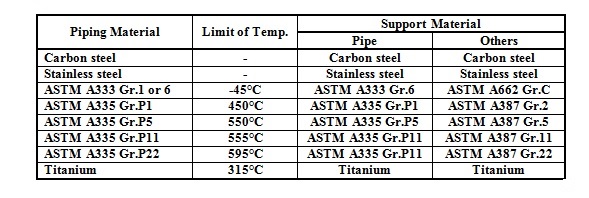
2.3.2. Support material, which is welded directly to piping, shall be chosen with the following table.
Material Selection Table

2.4. CONNECTIONS - PIPING HANGING AND SUPPORT
The connections of steel supports members can be bolted or welded.
2.4.1. Welds shall conform to the American Welding Society “Standard Code for Welding in Building Construction”.
2.4.2. Boltholes shall be punched or drilled. Flame cut holes is not acceptable.
2.5. SUPPORT SPAN - PIPING HANGING AND SUPPORT
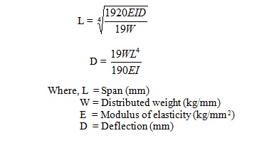
The following formula indicates maximum spans between supports.

a) Spans are based on a formula that gives a compromise between a beam with fixed ends, and a freely supported beam.
b) For lines operating above 200°C, support span should be checked with regard to allowable stress limitations at the specific temperature involved.
c) Spans shall generally be determined so that the deflection of piping by the weight of piping component, fluid and of insulation will not exceed 12 mm.
2.6. SUPPORT TYPE
Support types are defined as follows:
Anchor - A support fixing the pipe completely.
Guide - A support restricting the movement perpendicular to pipe axis, but the axial movement is allowed.
Hanger - A support hanging the piping.
Spring - A resilient support, which allows vertical movement.
Resting support - A simple support bearing the pipe weight only.
Directional stop - A support restricting the movement of a certain direction.
2.7. SUPPORT MARKING - PIPING HANGING AND SUPPORT
Support marking shall consist of an identification number, dimension, material and location etc.
2.8. FOUNDATION AND INSERT PLATE FOR PIPE SUPPORTS
2.8.1. Pipe support foundation elevation shall be minimum 150mm height from H.P.P (EL.= 0 for each terrace).
2.8.2. Pipe support foundations may be constructed at field in consideration of field condition unless which are shown on foundation drawing.
2.8.3. Insert plate must be considered when the support is to be installed on concreted and location with other requirements shall be informed to civil structural engineer.
2.9. DRAWING SYMBOL
Support symbols is shown on Standard Pipe Support Drawing.
3. EXECUTION AND ERECTION OF SUPPORTS - PIPING HANGING AND SUPPORT
3.1. GENERAL
3.1.1. Support design shall be executed for the 2” & larger lines include following 1-1/2” & smaller lines.
- Row of parallel pipes.
- Need of spring hanger, stops, etc.
3.1.2. Lines 2” and smaller insulated for heat conservation and personal protection shall rest on supports with the insulation cut back at the supports with no shoe required. Insulation shall be cut-back a sufficient amount to allow for line movement due to thermal expansion.
3.1.3. Pipe support field weld points shall be adjusted carefully at field in accordance with field condition.
3.1.4. Field welded pipe supports shall be set correctly in place and adjusted to the final position before welding to the piping or structures.
3.1.5. Pipe support shall be fabricated and installed in accordance with Pipe Support Drawings.
3.1.6. A shoe support shall be attached to the pipe in accordance with the drawings. It is not permitted to tack-weld a shoe to pipe rack, where the shoe support is not to permanently fix to the pipe rack.
3.1.7. Thermally expanding piping shall be fastened at the plant battery limits.
3.1.8. Horizontal piping expansion loops in pipe tracks or on pipe bridges shall have vertical offset to stay clear of adjacent piping.
3.1.9. Welding of support elements to galvanized piping or steel structure is not permitted.
3.1.10. All support assemblies which include plates, pipes, shape steels, bolts, nuts, springs and etc. shall be made by construction contractor according to standard drawings, except spring supports, clamps, cradles, lugs and blocks for cold insulation.
3.2. SPRING HANGERS
3.2.1. Spring hanger pin shall be removed only when the supported lines are ready for start-up condition.
3.2.2. The Pre-set pieces of the pipe hanger shall be removed after completion of leak test of the piping. However, pipelines, which will be insulated, it shall be removed after completion of the insulation work.
3.2.3. After plant has started operation, check the spring hanger position whether it is at hot load position and confirm any excess variation from design load.
3.3. PREFABRICATED PIPE SUPPORT
Pipe supports, which are located at high elevation, may be prefabricated at shop under supervision of piping field engineer. Piping field engineer will designate exact dimension of above mentioned pipe supports for its prefabrication.
4. PAINTING - PIPING HANGING AND SUPPORT
Pipe support painting shall be in accordance with requirements of “Engineering Specification for Painting”.
Free newsletter!
Sign up to receive my monthly newsletter covering all the latest courses and updates.


New! Comments
Have your say about what you just read! Leave me a comment in the box below.