Power Transformer Testing (FAT Test)
The power transformer testing (FAT Test) is performed after completion of the assembly at the manufacturing shop. You may also review power transfer inspection article for step by step inspection guideline or review power transformer inspection and test plan.

Measurement of Winding Resistance
The resistance of each winding shall be measured at ambient temperature. Measurement shall be carried out with direct current (DC) by the voltage drop method or the bridge method as specified in the manufacturer approved power transformer testing procedure.
Measurement of Voltage Ratio
The voltage ratio shall be measured on each tapping and verified aginst manufacturer approved power transformer testing procedure.
Check of Phase Displacement
The polarity of single-phase transformers and connection symbol of three-phase transformers shall be checked in each winding.
Measurement of No-Load Loss and Current in Power Transformer Testing

The no-load loss and no-load current shall be measured at the rated voltage and the rated frequency. The wave-form of the test voltage shall be an approximately sinusoidal wave.
Measurement of Short Circuit and Impedance and Load Loss
The short-circuit impedance and load loss shall be measured at the rated frequency and the rated current. When the measurement of the rated current is difficult, the test may be performed at reduced current to 50 % and above of the rated current. In this case, above measured value shall be converted into rated current.
Short-circuit impedance shall be measured with the windings connected on the principal tappings. Furthermore, the short-circuit impedance shall be measured with the winding connected on the maximum and minimum tappings.
Temperature Rise Test
The test shall be carried out by any one of the following methods.Direct loading method
Direct loading method
Rated load is applied to the transformer windings.
Back-to-back method
Rated current is applied to the transformer windings at rated voltage.
Equivalent loading method (short-circuit method)
To determine the temperature rise of oil, the input power corresponding to the sum of no-load and load losses shall be supplied to the transformer, one of its windings being excited and another short-circuited.
When the rate of change of top oil temperature rise has fallen below 1 K per hour, the input is reduced to a value which results in the flowing of rated current at rated frequency in the windings, and this value shall be maintained for three(3) hours. The temperature of the windings is then determined by resistance method.
When the winding is provided with taps, the temperature rise tests shall be carried out at the tap which makes the total losses maximum.
The temperature rise test shall be carried out on the following items:
- Maximum temperature rise of oil
- Temperature rise of windings
- Temperature rise of core and other metallic parts when specified.
Insulation Resistance Test
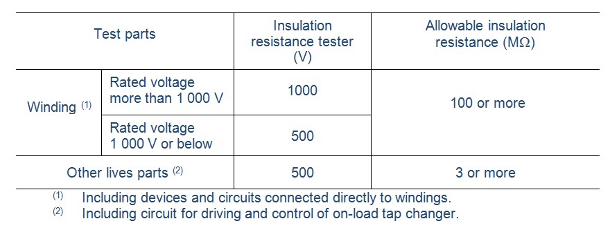
The insulation resistance between all windings or other live parts of the transformers and ground (or casing) shall be measured, and the insulation resistance tester and allowable insulation resistance value for each part shall be as follows, or specified values in the manufacturer approved power transformer testing procedure.

Induced Overvoltage Withstand Test

The test shall be carried out by applying an alternating voltage as nearly of sinusoidal wave form as possible and a frequency higher than the rated frequency, to the terminals of one winding of the transformer.
Separate-Source Voltage Withstand Test
The separate-source voltage test shall be carried out with single-phase alternating voltage as nearly of sinusoidal wave form as possible and of any convenient frequency not loss than 80 % of the rated frequency.
For live parts of accessories (except on-load tap changer), test voltage (2E+1 000 V) shall be applied for 1 minute, and no electrical or mechanical defects shall be found. (Where E means the rated voltage.)
Lightning Impulse Test
Impulse test voltage specified in applicable standard shall be applied to the windings of high voltage side of transformers designed for lightning impulse test.
Calculation For Losses And Characteristic Value
The following losses and characteristic values shall be calculated from the results of "Winding Resistance Test", "No-Load Loss and Current Test" and "Short Circuit Impedance and Load Loss Test" and shall be compared with manufacturer approved test procedure acceptance criteria.
1- Losses
- No-load loss
- Load loss
2- Characteristic Values
- Short circuit impedance
- Voltage regulation
- Conventional efficiency
Measurement Of Noise
Measurement of the sound level of transformers shall be carried out when specially specified as for large size transformers. Measuring method shall be by the relevant IEC standards.
Free newsletter!
Sign up to receive my monthly newsletter covering all the latest courses and updates.


New! Comments
Have your say about what you just read! Leave me a comment in the box below.