Pressure Vessel RT Test
The Pressure Vessel RT Test article provides you with information about Radiography testing in the pressure vessel manufacturing process and related items in pressure vessel inspection.
The pressure vessel radiography test is addressed in API 510 pressure vessel inspector online training course in the ASME Section VIII Div.1 Section. It is also covered in the I4I Academy ASME Training course.
Do you know what your pressure vessel RT test requirements are? Is full radiography mandatory for your vessel? When is full radiography mandatory? What are the acceptance criteria? What are the RT symbols?
So if you need this information, this article answers all of these questions.
We recommend that you to review this article in conjunction with the ASME Pressure Vessel Joint Efficiencies article.
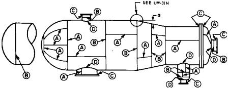
Before going into the RT test, we need to know about joint categories. These categories are base on ASME Code Section VIII:

Category A:
- All longitudinal welds in shell and nozzles.
- All welds in heads, Hemisph-head to shell weld joint
Category B:
- All circumferential welds in shell and nozzles
- Head to shell joint (other than Hemisph.)
Category C and D are flange welds and nozzle attachment welds respectively
Longitudinal weld (Category A) is more critical because it is subjected to double the stress than Circ. Weld (Category B) and this the reason in different part of the ASME code, we have stringent rules in category A joints compared to category B joints.
Pressure Vessel RT Test -When We Need to Do a Full Radiography Test?
When one of following conditions is existing, you need to do the full radiography:
- All butt welds in vessels used to contain a lethal substance
- All butt welds in vessels in which the nominal thickness exceeds specified values
- All butt welds in unfired steam boilers with design pressure > 50 psi
- All category A and D butt welds in a vessel when “Full Radiography” is optionally selected
As you see, the item numbers 1, 2 and 3 are really mandatory for a full RT test;
But pressure vessel manufacturers can make an optional decision for full radiography in item number 4
Pressure Vessel RT Test - Why do pressure vessel manufacturers want to spent more money for full radiography in item # 4?
Because the joint efficiency in the full radiography condition is 1, the higher joint efficiency in the pressure vessel wall thickness formula causes less wall thickness. The manufacturer might save lots of money with a lower thickness plate material.
But code has given some bonus to manufacturers in item 4, because it is not mandated to do full radiography in all butt welds. Manufacturers can do spot radiography in B and C joints with the same joint efficiency of item 1.
Item number 2 describes thickness limitations. Any pressure vessel material is designated to the specific P. Number by ASME section IX, so there are several tables in ASME Code Section VIII Div. 1 Subsection C, which determine this limitation.
For example, SA 516 material is P Number 1, and needs to be fully radiographed if its thickness is greater than 1.25 of an inch. At the same time, SA 204 material is P Number 3 and needs to be fully radiographed if the thickness is greater than 0.75 of an inch.
Pressure Vessel RT Test - Is Acceptance Criteria in Full Radiography or in Spot Radiography More Stringent?
Acceptance criteria for welding defects in full radiography is stringent. These criteria are stated in UW-51 and UW-52 in ASME Code Section VIII Div. 1
It means there is a defect if interpreted based on the full radiography criteria in UW-51, and it might be rejected, but if it is interpreted by the spot radiography criteria in UW-52, it might be accepted.
Pressure Vessel RT Test - What is the Important Spot Radiography Requirement?
- One spot shall be examined on each vessel for each 50 ft. increment
- For each increment of weld to be examined, a sufficient number of spot radiographs will be taken to examine the welding of each welder or welding operator
- Each spot examination will be made as soon as practicable after the completion of the increment of weld to be examined
- The location of the spot shall be chosen by the Inspector after the completion of the increment of welding to be examined
Pressure Vessel RT Test - Radiographic Personnel Qualification:
The radiographic personnel need to be certified by the pressure vessel manufacturer according to their written practice.
Holding the ASNT Radiographic certificate is not enough
In fact, SNT-TC-1A can be used as a guideline for manufacturers to establish their written practice for qualification and certification of their personnel.
Radiographic Examination Procedure and method
ASME Code Section VIII Div 1 mandates that all tests shall be done based on ASME Code Section V, article number 2.
Free newsletter!
Sign up to receive my monthly newsletter covering all the latest courses and updates.


New! Comments
Have your say about what you just read! Leave me a comment in the box below.