Uninterrupted Power Supply Testing (UPS Testing)
The uninterrupted power supply testing shall be performed after completion of assembly in the manufacturing shop.
Insulation Resistance Test

The insulation resistance of the following circuit shall be measured by 500 V insulation resistance tester (or with the range that specified in approved test procedure), before and after voltage withstand test, and the each resistance value shall be 3 M Ohm and above (or as specified in the approved uninterrupted power supply testing procedure). In the case of an earthed circuit, it is the value when the earthing connection is removed.
- Between the a-c live part and cubicle
- Between the d-c live part and cubicle
- Between the a-c live part and the d-c live part

Power Frequency Voltage Withstand Test
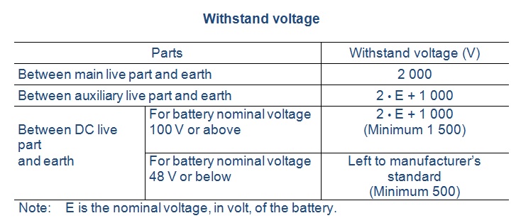
The 50 Hz or 60 Hz test voltage shall be applied for 1 minute to the parts as shown in the following table (or as specified in the supplier approved test procedure), and no defects shall be found. The semiconductors, electrolytic condensers (for smoothing filter) and electronic control devices are removed, before the test. In the case of an earthed circuit, it is the value when the earthing connection is removed.
Operation Test @ Uninterrupted Power Supply Testing
The test shall be carried out using power source device or test battery and simulated load for:
- Function of start/stop/change-over / float charge /equalizing charge / full load operation and their indicator at normal condition.
- Protective function against abnormality/failure and indicative function of alarm devices.
The operation of UPS shall meet the acceptance criteria that indicated in the manufacturer approved test procedure.
A-C Output Characteristic Test
The a-c output characteristic test shall be carried out together by providing the combination of power source device or simulated battery and simulated load, and shall be confirmed that the test results shall satisfy the performance specified in the approved data sheets or UPS manufacturer approved test procedure.
Voltage Adjustment Range Test
When the a-c input voltage and the a-c output current shall be set at the rated value, the a-c output voltage adjustment range shall be measured (when the set of the voltage regulator is within the lower limit or upper limit), and variable range shall be not less than the specified value in the approved procedure.
Output Voltage Accuracy Test
When the a-c input voltage shall be set at the rated value, the variation of the a-c output voltage shall be measured, in each case of the a-c output current, being 0 %, 50 % and 100 % of the rated current and the accuracy shall be within the specified limit as indicated in manufacturer approved uninterrupted power supply testing procedure.
Transient Output Voltage Characteristic Test
The transient output voltage characteristic test shall be carried out to verify that the transient fluctuation in output voltage falls within the specified limit ( for the rated condition).
Frequency Accuracy Test
Frequency accuracy shall be confirmed to be within the specified limit.
Output Voltage Waveform Distortion Test
Output voltage waveform distortion test shall be carried out as follows:
For linear load:
Output voltage waveform distortion for the linear load of the rated output capacity and rated power factor shall be within the specified limit.
For non-linear load (such as rectifiers):
Output voltage waveform distortion for the load of the rated output capacity which includes non-linear load (such as rectifiers) of 50 % the rated output capacity with higher harmonics shall be within the specified limit.
Overload Capability Test
Overload capability of UPS shall be ensured to endure for the overload condition mentioned in the manufacturer approved UPS testing procedure.
Output Voltage Unbalance Test
Output voltage unbalance of UPS with three-phase output shall be measured and the value shall be confirmed to be within the specified value.
Temperature Rise Test
Temperature rise (measured by the thermometer) of UPS shall not exceed the limits given in the applicable standards when operated at the rated output, the rated a-c input voltage, and the rated frequency.
Efficiency and Input Power Factor Test
After the temperature rise test, the input power shall be measured at the condition of the rated input voltage, the rated input frequency, and the rated output capacity. The efficiency and input power factor of UPS shall be calculated, based on the obtained data.
The efficiency and power factor shall conform to the manufacturer approved test procedure.
Noise Test @ Uninterrupted Power Supply Testing
Sound pressure level shall be measured at four positions, 1 meter from the panel surface, using an A-weighting network as specified. The noise level should not be more than 85 decibels.
Free newsletter!
Sign up to receive my monthly newsletter covering all the latest courses and updates.


New! Comments
Have your say about what you just read! Leave me a comment in the box below.